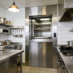
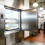
Product Type: Traction-type window-type dumbwaiter (food elevator / service elevator)
Rated Load Capacity: 200kg
Stations: 3 stops, 3 landings
Door Style: Window-type (landing sill height approx. 750mm)
Standards Applied: GB 25194-2010, TSG T7006-2012
1 Technical Specifications
- Rated load: 200kg
- Rated speed: 0.4 m/s
- Control mode: PLC microcomputer control, hall call operation
- Driving mode: Traction machine (worm gear or permanent magnet synchronous)
- Car inner dimensions (reference): W800mm × D800mm × H1000mm
- Landing door type: Vertical sliding door / center opening door (window type)
- Power supply: 380V AC, 50Hz, 3-phase 5-wire
- Recommended shaft dimensions: W1200mm × D1000mm
- Pit depth: ≥ 800mm
- Top floor height: ≥ 3000mm
- Leveling accuracy: ±5mm
2 Pre-installation Preparation
2.1 Site Conditions
- The hoistway must be vertical and free of obstacles; vertical tolerance ≤ 5mm per 5m.
- The pit must be dry, waterproof, and free of water accumulation.
- The top floor space must be sufficient for traction machine installation.
- Power supply shall be ready: 380V, 5–10kW, with reliable grounding.
2.2 Required Tools
- Level gauge, plumb bob, measuring tape, square ruler
- Hand hoist, impact drill, wrenches, screwdrivers
- Multimeter, 500V megohmmeter
- Scaffolding, safety harnesses, warning signs
2.3 Component Checklist
Car body, 3 sets of landing doors, car door, guide rails, counterweight, traction machine, steel wire ropes, control cabinet, 3 hall call panels, door locks, buffers, limit switches, etc.
3 Installation Procedures
3.1 Setting Out and Positioning
- Mark the center lines of the car, counterweight and door sills.
- Ensure the three landing sills are vertically aligned with deviation ≤ 3mm.
3.2 Pit Component Installation
- Install car buffer and counterweight buffer.
- Install pit inspection light and emergency stop switch.
- Fix buffers firmly and ensure horizontal and vertical alignment.
3.3 Guide Rail Bracket and Guide Rail Installation
- Guide rail bracket spacing ≤ 2m; at least 2 brackets per rail.
- Install car guide rails and counterweight guide rails.
- Verticality adjusted to ≤ 0.5mm/m, total deviation ≤ 1.5mm.
- Rail joints shall be smooth and level without steps.
3.4 Landing Sill and Door Installation (3 Floors)
- Install 1F, 2F, 3F door sills with horizontality ≤ 1/1000.
- Install landing door frames, door panels and door lock devices.
- Adjust door pulleys and slides for smooth operation.
- Each landing door must be equipped with mechanical lock + electrical interlock switch.
- Door gaps shall be uniform and well sealed when closed.
3.5 Car Assembly
- Assemble the car frame at the pit or middle shaft.
- Install car wall, car floor and car roof.
- Install car door, door operator, guide shoes and safety gear.
- Car diagonal dimension tolerance ≤ 2mm.
- Window heights shall be consistent for convenient food transfer.
3.6 Traction Machine Installation
- Install load-bearing steel beam and traction machine base.
- Adjust verticality and horizontality of the traction sheave.
- Adjust brake clearance to ensure reliable braking.
- Secure all wiring connections.
3.7 Steel Wire Rope and Counterweight Installation
- At least 2 steel wire ropes, diameter ≥ 6mm.
- Fix rope sockets firmly and reliably.
- Install counterweight frame and counterweight blocks.
- Adjust wire rope tension to be uniform.
3.8 Electrical System Installation
- Install the control cabinet on the top floor or machine room.
- Lay power cables, control cables and grounding wires.
- Install 3 sets of hall call panels, floor indicators and leveling sensors.
- Connect limit switches, final limit switches, door interlocks and emergency stop circuits.
- Insulation resistance requirements:
- Power circuit ≥ 0.5 MΩ
- Control circuit ≥ 1 MΩ
- Grounding resistance ≤ 4 Ω
4 Commissioning and Testing
4.1 Slow-speed Inspection Commissioning
- Jog up and down to check for jamming or abnormal noise.
- Adjust upper and lower limit positions.
- Test safety gear linkage and brake action.
4.2 Automatic High-speed Commissioning
- Set floor address codes (1F, 2F, 3F).
- Adjust leveling accuracy within ±5mm.
- Test hall calls, arrival chime, automatic door opening and delayed closing.
- Verify three-story door interlocks: elevator cannot start if any door is open.
4.3 Load Testing
- No-load operation: smooth movement, no abnormal noise.
- Rated load (200kg) operation: accurate leveling, no slipping.
- 125% overload test (250kg):
- The elevator alarms and prohibits starting.
- Brake holds reliably; no structural deformation.
4.4 Safety Function Tests
- Door open operation protection
- Emergency stop function
- Overload protection
- Upper and lower final limit protection
- Emergency lighting test
5 Acceptance Standards (for 3-stop window-type dumbwaiter)
- All three landing door interlocks are effective and securely closed.
- Window heights are consistent for safe and convenient food transfer.
- Leveling is accurate with no obvious height difference.
- Operation is smooth without shaking or abnormal noise.
- Floor display is correct and hall calls respond timely.
- The pit is dry and buffers are effective.
- Grounding and insulation resistance meet requirements.
6 Safety Instructions
After installation, the dumbwaiter must pass inspection by the local special equipment inspection institute before formal use.
Installation must be performed by certified special equipment technicians.
Personnel working in the hoistway must wear safety helmets and safety harnesses.
Riding in the dumbwaiter is strictly prohibited. Do not exceed 200kg rated load.